- 您现在的位置:买卖IC网 > Sheet目录1214 > EVAL-ADUM3221AEBZ (Analog Devices Inc)BOARD EVAL FOR ADUM3220/ADUM3221
�� �
�
�Data� Sheet�
�Output� ringing� can� be� reduced� by� adding� a� series� gate� resistor�
�to� dampen� the� response.� For� applications� that� use� a� load� of� 1� nF�
�or� less,� it� is� recommended� that� a� series� gate� resistor� of� about� 5� ?�
�be� added.� As� shown� in� Figure� 7,� R� GATE� is� 5� ?,� which� yields� a�
�calculated� Q� factor� of� about� 0.3.� Figure� 7� illustrates� a� damped�
��DC� CORRECTNESS� AND� MAGNETIC� FIELD� IMMUNITY�
�Positive� and� negative� logic� transitions� at� the� isolator� input� cause�
�narrow� (~1� ns)� pulses� to� be� sent� to� the� decoder� via� the� transformer.�
�The� decoder� is� bistable� and� is,� therefore,� either� set� or� reset� by� the�
�pulses,� indicating� input� logic� transitions.� In� the� absence� of� logic�
�100�
�10�
�1�
�0.1�
�0.01�
�ADuM3220/ADuM3221�
�transitions� of� more� than� 1� μs� at� the� input,� a� periodic� set� of� refresh�
�pulses� indicative� of� the� correct� input� state� is� sent� to� ensure� dc�
�0.001�
�1k�
�10k� 100k� 1M� 10M�
�MAGNETIC� FIELD� FREQUENCY� (Hz)�
�100M�
�correctness� at� the� output.�
�If� the� decoder� receives� no� internal� pulses� for� more� than� about�
�3� μs,� the� input� side� is� assumed� to� be� unpowered� or� nonfunc-�
�tional,� in� which� case� the� isolator� output� is� forced� to� a� default�
�low� state� by� the� watchdog� timer� circuit.� In� addition,� the� outputs�
�are� in� a� low� default� state� while� the� power� is� rising� before� the�
�UVLO� threshold� is� crossed.�
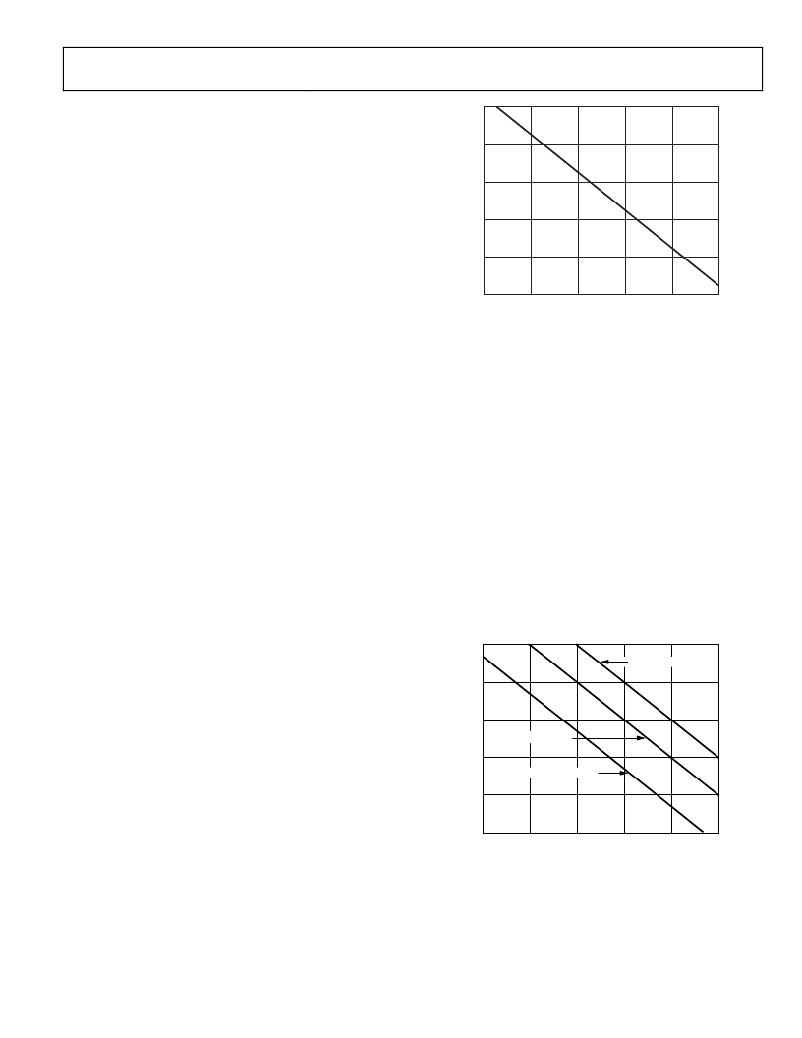
�The� ADuM3220� /� ADuM3221� are� immune� to� external� magnetic�
�fields.� The� limitation� on� the� ADuM3220� /� ADuM3221� magnetic�
�field� immunity� is� set� by� the� condition� in� which� induced� voltage�
�in� the� transformer� receiving� coil� is� sufficiently� large� to� either�
�falsely� set� or� reset� the� decoder.� The� following� analysis� defines�
�the� conditions� under� which� this� can� occur.� The� 3� V� operating�
�condition� of� the� ADuM3220� /� ADuM3221� is� examined� because�
�it� represents� the� most� susceptible� mode� of� operation.� The� pulses�
�at� the� transformer� output� have� an� amplitude� greater� than� 1.0� V.�
�The� decoder� has� a� sensing� threshold� at� about� 0.5� V,� therefore�
�establishing� a� 0.5� V� margin� in� which� induced� voltages� can� be�
�tolerated.� The� voltage� induced� across� the� receiving� coil� is� given� by�
�V� =� (� ?dβ� /� dt� )� ∑� π� r� n� 2� ;� n� =� 1,� 2,� ...� ,� N�
�Figure� 22.� Maximum� Allowable� External� Magnetic� Flux� Density�
�For� example,� at� a� magnetic� field� frequency� of� 1� MHz,� the� maxi-�
�mum� allowable� magnetic� field� of� 0.2� kgauss� induces� a� voltage�
�of� 0.25� V� at� the� receiving� coil.� This� is� about� 50%� of� the� sensing�
�threshold� and� does� not� cause� a� faulty� output� transition.� Simi-�
�larly,� if� such� an� event� were� to� occur� during� a� transmitted� pulse�
�(and� had� the� worst-case� polarity),� the� received� pulse� is� reduced�
�from� >1.0� V� to� 0.75� V,� still� well� above� the� 0.5� V� sensing� thresh-�
�old� of� the� decoder.�
�The� preceding� magnetic� flux� density� values� correspond� to�
�specific� current� magnitudes� at� given� distances� away� from� the�
��these� allowable� current� magnitudes� as� a� function� of� frequency�
��are� immune� and� can� be� affected� only� by� extremely� large� currents�
�operated� at� a� high� frequency� very� close� to� the� component.� For�
�the� 1� MHz� example,� a� 0.5� kA� current� must� be� placed� 5� mm�
�away� from� the� ADuM3220� /� ADuM3221� to� affect� the� operation�
�of� the� component.�
�1000�
�where:�
�β� is� the� magnetic� flux� density� (gauss).�
�r� n� is� the� radius� of� the� nth� turn� in� the� receiving� coil� (cm).�
�N� is� the� number� of� turns� in� the� receiving� coil.�
��100�
�10�
�DISTANCE� =� 100mm�
�DISTANCE� =� 1m�
�ADuM3221� and� an� imposed� requirement� that� the� induced�
�voltage� be,� at� most,� 50%� of� the� 0.5� V� margin� at� the� decoder,�
�a� maximum� allowable� magnetic� field� is� calculated,� as� shown�
��1�
�0.1�
�0.01�
�DISTANCE� =� 5mm�
�1k�
�10k�
�100k�
�1M�
�10M�
�100M�
�MAGNETIC� FIELD� FREQUENCY� (Hz)�
�Figure� 23.� Maximum� Allowable� Current� for� Various�
�Current-to-� ADuM3220� /� ADuM3221� Spacings�
�Rev.� C� |� Page� 13� of� 16�
�发布紧急采购,3分钟左右您将得到回复。
相关PDF资料
EVAL-ADUM3471EBZ
EVALUATION MODULE FOR ADUM3471
EVAL-ADUM4160EBZ
EVALUATION MODULE FOR ADUM4160
EVAL-ADUM4223AEBZ
BOARD EVAL FOR ADUM4223
EVAL-ADUMQSEBZ
EVAL BOARD FOR ICOUPLER SMD
EVAL-ADUSB2EBUZ
BOARD EVAL USBI
EVAL-ADV7195EB
BOARD EVAL FOR ADV7195
EVAL-ADV7401EBZ
BOARD EVALUATION FOR ADV7401
EVAL-ADV7403EBZ
BOARD EVALUATION FOR ADV7403
相关代理商/技术参数
EVAL-ADUM3223AEBZ
功能描述:BOARD EVAL FOR ADUM3223 RoHS:是 类别:编程器,开发系统 >> 评估演示板和套件 系列:iCoupler® 标准包装:1 系列:- 主要目的:数字电位器 嵌入式:- 已用 IC / 零件:AD5258 主要属性:- 次要属性:- 已供物品:板 相关产品:AD5258BRMZ1-ND - IC POT DGTL I2C1K 64P 10MSOPAD5258BRMZ10-ND - IC POT DGTL I2C 10K 64P 10MSOPAD5258BRMZ100-ND - IC POT DGTL I2C 100K 64P 10MSOPAD5258BRMZ50-ND - IC POT DGTL I2C 50K 64P 10MSOPAD5258BRMZ1-R7-ND - IC POT DGTL I2C 1K 64P 10MSOPAD5258BRMZ10-R7-ND - IC POT DGTL I2C 10K 64P 10MSOPAD5258BRMZ50-R7-ND - IC POT DGTL I2C 50K 64P 10MSOPAD5258BRMZ100-R7-ND - IC POT DGTL I2C 100K 64P 10MSOP
EVAL-ADUM330X
制造商:AD 制造商全称:Analog Devices 功能描述:Quad Isolators with isoPower Evaluation Board
EVAL-ADUM340X
制造商:AD 制造商全称:Analog Devices 功能描述:Quad Isolators with isoPower Evaluation Board
EVAL-ADUM3471EBZ
功能描述:EVALUATION MODULE FOR ADUM3471 RoHS:是 类别:编程器,开发系统 >> 评估演示板和套件 系列:iCoupler® 标准包装:1 系列:- 主要目的:数字电位器 嵌入式:- 已用 IC / 零件:AD5258 主要属性:- 次要属性:- 已供物品:板 相关产品:AD5258BRMZ1-ND - IC POT DGTL I2C1K 64P 10MSOPAD5258BRMZ10-ND - IC POT DGTL I2C 10K 64P 10MSOPAD5258BRMZ100-ND - IC POT DGTL I2C 100K 64P 10MSOPAD5258BRMZ50-ND - IC POT DGTL I2C 50K 64P 10MSOPAD5258BRMZ1-R7-ND - IC POT DGTL I2C 1K 64P 10MSOPAD5258BRMZ10-R7-ND - IC POT DGTL I2C 10K 64P 10MSOPAD5258BRMZ50-R7-ND - IC POT DGTL I2C 50K 64P 10MSOPAD5258BRMZ100-R7-ND - IC POT DGTL I2C 100K 64P 10MSOP
EVAL-ADUM3481EBZ
制造商:Analog Devices 功能描述:EVALUATION BOARD DIGITAL ISOLATOR - Boxed Product (Development Kits)
EVAL-ADUM4070EBZ
功能描述:界面开发工具 RoHS:否 制造商:Bourns 产品:Evaluation Boards 类型:RS-485 工具用于评估:ADM3485E 接口类型:RS-485 工作电源电压:3.3 V
EVAL-ADUM4160EBZ
功能描述:EVALUATION MODULE FOR ADUM4160 RoHS:是 类别:编程器,开发系统 >> 评估演示板和套件 系列:iCoupler® 标准包装:1 系列:- 主要目的:电信,线路接口单元(LIU) 嵌入式:- 已用 IC / 零件:IDT82V2081 主要属性:T1/J1/E1 LIU 次要属性:- 已供物品:板,电源,线缆,CD 其它名称:82EBV2081
EVAL-ADUM4160EBZ RENT
制造商:Analog Devices 功能描述:BOARD EVAL DIGITAL ISOLATOR